CWDM SFP+
| Part No. |
Description |
Data Rate |
Wavelength |
Distance |
Connector |
Temp. |
| EOLP-1696-10X |
CWDM SFP+ LR |
9.95~11.1G |
1270~1610nm |
10dB |
LC |
C |
| EOLP-1696-14X |
CWDM SFP+ LR |
9.95~11.1G |
1270~1610nm |
14dB |
LC |
C |
| EOLP-1696-23X |
CWDM SFP+ ER |
9.95~11.1G |
1270~1450nm |
23dB |
LC |
C |
| EOLP-1696-14XN |
CWDM SFP+ ER |
9.95~11.1G |
1470~1610nm |
14dB |
LC |
C |
| EOLP-1696-14XEN |
CWDM SFP+ ER |
9.95~11.1G |
1470-1610nm |
14ddB |
LC |
E |
| EOLP-1696-23XN |
CWDM SFP+ ZR |
9.95~11.1G |
1470~1610nm |
23dB |
LC |
C |
| EOLP-1696-23XEN |
CWDM SFP+ ZR |
9.95~11.1G |
1470-1610nm |
23dB |
LC |
E |
For the latest specification and samples, please, contact us This email address is being protected from spambots. You need JavaScript enabled to view it.
CWDM SFP+ CDR
| Part No. |
Description |
Data Rate |
Wavelength |
Distance |
Connector |
Temp. |
| EOLP-1696-14XR |
CWDM SFP+ ER CDR |
9.95~11.1G |
1270~1450nm |
14dB |
LC |
C |
| EOLP-1696-14XRN |
CWDM SFP+ ER CDR |
9.95~11.1G |
1470~1610nm |
14dB |
LC |
C |
| EOLP-1696-23XRN |
CWDM SFP+ ZR CDR |
9.95~11.1G |
1470~1610nm |
23dB |
LC |
C |
For the latest specification and samples, please, contact us This email address is being protected from spambots. You need JavaScript enabled to view it.
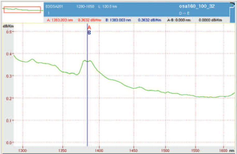
Attenuation in 652D fiber vs CWDM wavelenght
 Talking about CWDM modules, it's more correct to talk about optical budget rather then distance talking into account that IL per different CWDM wavelength is different in fiber.
he optical power budget in a fiber-optic communication link is the allocation of available optical power (launched into a given fiber by a given source) among various loss-producing mechanisms such as launch coupling loss, fiber attenuation, splice losses, and connector losses, in order to ensure that adequate signal strength (optical power) is available at the receiver. In optical power budget attenuation is specified in decibels (dB) and optical power in dBms.
The amount of optical power launched into a given fiber by a given transmitter depends on the nature of its active optical source (LED or laser diode) and the type of fiber, including such parameters as core diameter and numerical aperture. Manufacturers sometimes specify an optical power budget only for a fiber that is optimum for their equipment—or specify only that their equipment will operate over a given distance, without mentioning the fiber characteristics. The user must first ascertain, from the manufacturer or by testing, the transmission losses for the type of fiber to be used, and the required signal strength for a given level of performance.
In addition to transmission loss, including those of any splices and connectors, allowance should be made for at least several dB of optical power margin losses, to compensate for component aging and to allow for future splices in the event of a severed cable.
LT = αL + Lc + Ls
Definitions:
LT - Total loss
α - Fiber attenuation
L - Length of fiber
Lc - Connector loss
Ls - Splice loss


 Talking about CWDM modules, it's more correct to talk about optical budget rather then distance talking into account that IL per different CWDM wavelength is different in fiber.